Home | Model Making | Writing | Photography | Biography | Contact | Links | Blog
 |
|
U.S.S. Carondelet. Scratch-build. 1/96th scale, StyreneAfter many years of taking perfectly good model kits, removing the majority of the detail, and then proceeding to rebuild it all to my standards, I've decided to take the leap and just do it all myself. First, a little about the original ship. |
|
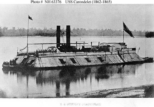
U.S.S. Carondelet was one of the City Class gunboats, a class of 7 gunboats that were purposely built after the start of the war for service on the western rivers. They were somewhat odd in this respect as most of the ships used in the west were conversions of existing ships. They were also unique in that they were only partial ironclads; very little of their upper works and none of their hulls were iron plated. Carondelet was launched in October of 1861, commissioned in January of 1862. She saw much action during the war working to reduce Confederate forts and positions and, working directly with the Army during numerous occasions. These boats in fact were initially manned by Army crews, later turned over to Navy control. The rivers in the Western Theater allowed a cooperation between the Army and Navy during battles that wasn't possible in the Eastern Theater; Carondelet herself helped turn the Confederate flank during the battle at Nashville on December 15-16th, 1864. As stated these ships were partially armored, the only plating was on the pilot house, the forward casemate, and along the hull sides abreast of the boilers. The rest of the hull, decking and casemate were unprotected wood. This lack of armor came to haunt Carondelet on July 15, 1862 when she engaged the Confederate ironclad CSS Arkansas near Vicksburg. The more heavily armored Arkansas disabled the Carondelet and she had to be run aground to avoid sinking, suffering 35 casualties. She was refloated, refit, reinforced, and served through the rest of the war from Vicksburg to the Red River campaign, modified several times, and finished the war as the most engaged ship on either side of the conflict. In fact it would be WWII before another US ship would see more action, and she was the most famous of the Western Theater ships until her sister USS Cairo was found and raised in the 1960s. USS Carondelet was sold immediately after the war, used as a wharf boat at Gallipolis, Ohio, until she was washed away by the spring 1873 flood and washed up on Manchester Island near Manchester, Ohio. She lay there undisturbed until May 1982 when the author Clive Cussler found her... exactly two days after river dredging started over her exact location. Bits and pieces of the boat were found in the muck the dredge boat spit out, and some more of the Carondelet is thought to be embedded in the Ohio River bottom at that location, but the majority of the famous warship was destroyed in the dredging operation. |
|
I've started a running Reference and Supplies page for quick reference to any of the plans, publications, websites, tools or supplies that I use during this build. |
|
image courtesy of David Meagher |
|
| Construction | |
| I'm using .060 sheet styrene for the initial structures of decks and frames. I will then sheet that in two layers of .030 styrene, taking the thickness of all sheets into consideration. For plans I am using two sets from David Meagher; his 1/96th scale set from 1994, and a new 1/48th set that he has not yet released to the public (he in fact has not even fully finished the latter set). I also have a set of CAD drawings that were posted on a now dissolved Yahoo message group concerning Carondelet's sister USS Cairo. I have only found two or three actual photos of Carondelet, which I will post when appropriate during the build. | |
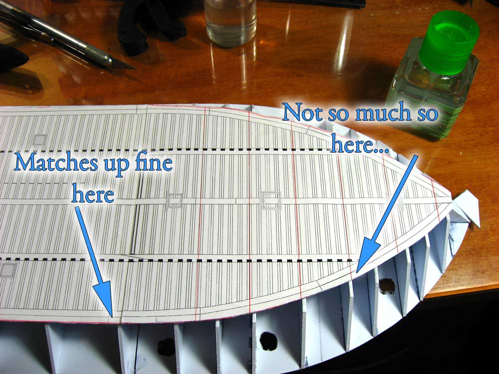
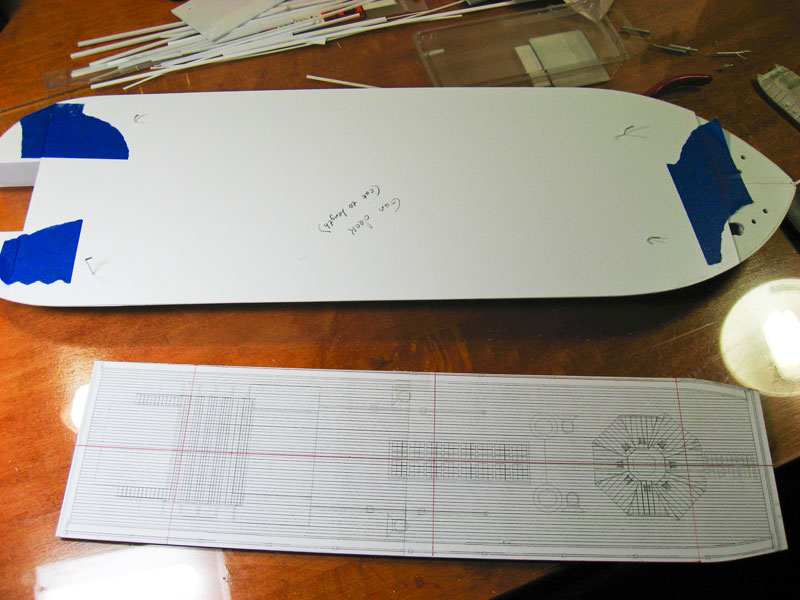
| I began by taking everything relevant and scanning it into the computer and resizing it to the proper size in Photoshop. These plans were then printed out, taped together (the overall length of the main deck is longer than my 8.5 X 11" printer capacity) and then affixed to sheet styrene. This was cut out using the score-and-snap method on the straight runs of the deck. The curve of the bow and stern were then cut using a Dremel jigsaw that I borrowed from Gary Kingzett. As I assemble this I find that my straight runs, while straight in the strict "looking at it from overhead" sense, have a little wobble in them through the thickness of the plastic. I can only assume this is from the knife blade waggling back and forth as I cut. Maybe less pressure and more passes are required. | 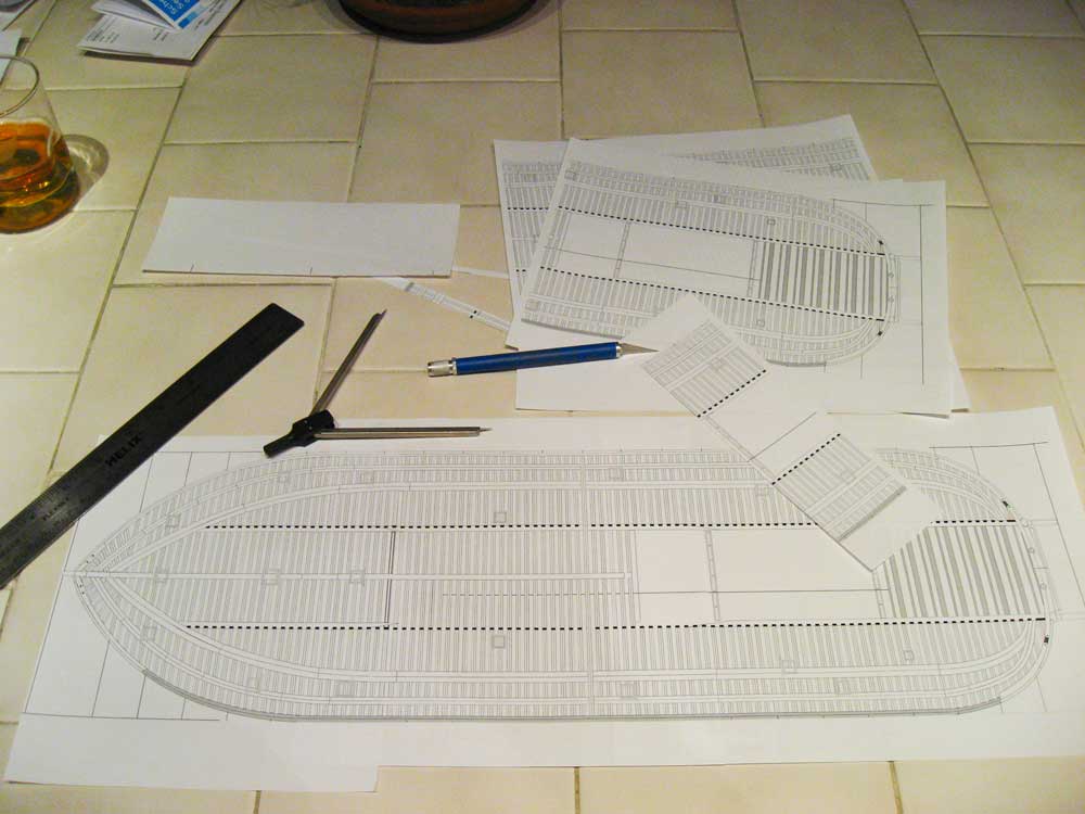 |
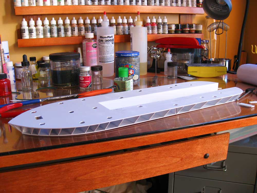
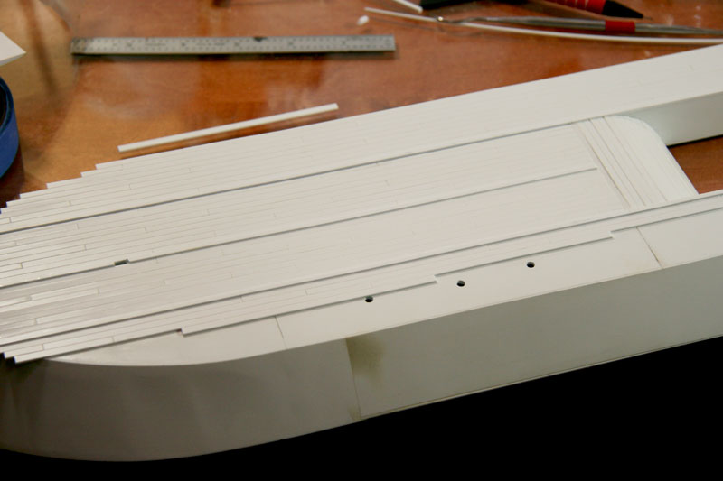
| The main deck cut out. These ships were of the mid-wheel paddle wheel design, the channel down the middle of the deck is for the paddle wheel to extend down through and the engine room to extend up through. The holes drilled in the deck will be the main deck passages for ammo and other stores to pass through; I drilled them through the .060 plastic and will square the .030 planking that will go over this as the thinner plastic will be much easier to cut square holes into. | 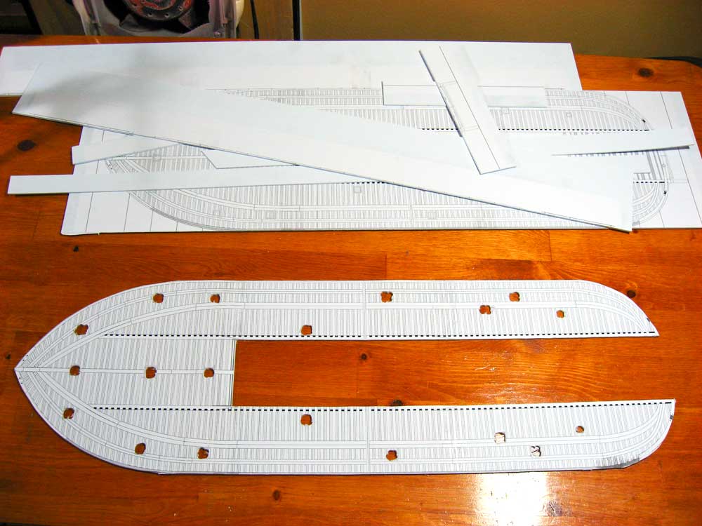 |
| To cut the frames that are glued onto the bottom of the main deck I calculated I needed stock exactly 21mm tall. As luck would have it, I have a strip styrene/wood cutter from Micro-Mark that just happens to have a maximum extension of exactly 21 mm. I couldn't ask for better luck. Since the upper and lower hull on the Carondelet are perfectly parallel at every point, then every frame is the same height from bow to stern, from inside to out. | 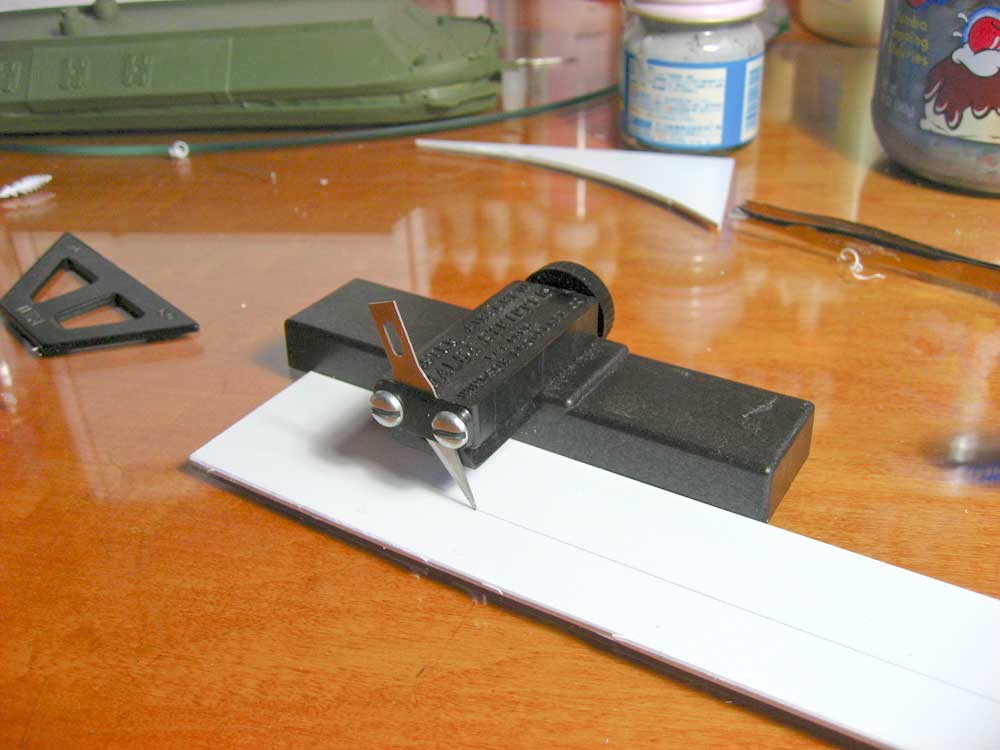 |
| Another easy aspect of this build is MOST of the angles on the hull are 45-degrees (more on that capitalized MOST later). To begin, I simply measured how wide the hull is where the frame goes, cut a 21mm tall strip of plastic to length, put it on the Chopper II and cut each end to 45-degrees, then glue it in place. I couldn't be any more simple; hard for even me to screw up! | 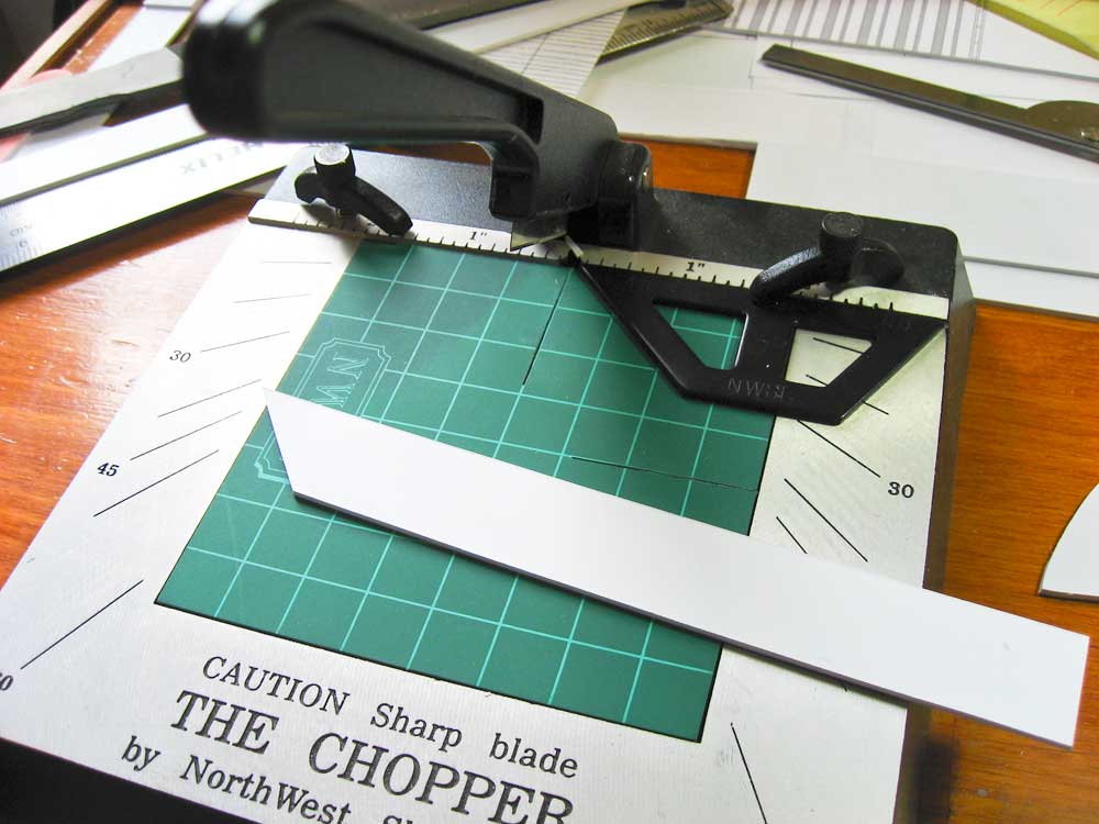 |
| Assembly proceeded rather quickly for my first build. Here you can see that I've put in bulkheads to encase the hull around the opening for the paddle wheel, the associate channel in the hull from the paddle wheel to the stern for the water, and forward of the paddle wheel where the boilers and furnace sit on the lower hull and extend up through the main deck. All plastic show here is still the .060 sheet styrene, purchased in a large 4' X 6' sheet in Chinatown for about 1/4 the cost of getting it through a hobby shop. I'm using Tamiya Thin Cement for the first time. Amazing stuff. It does a wonderful job of melting and bonding the styrene FAST, just be careful of the strong fumes. | 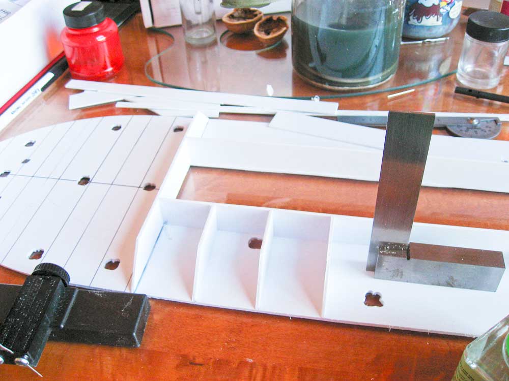 |
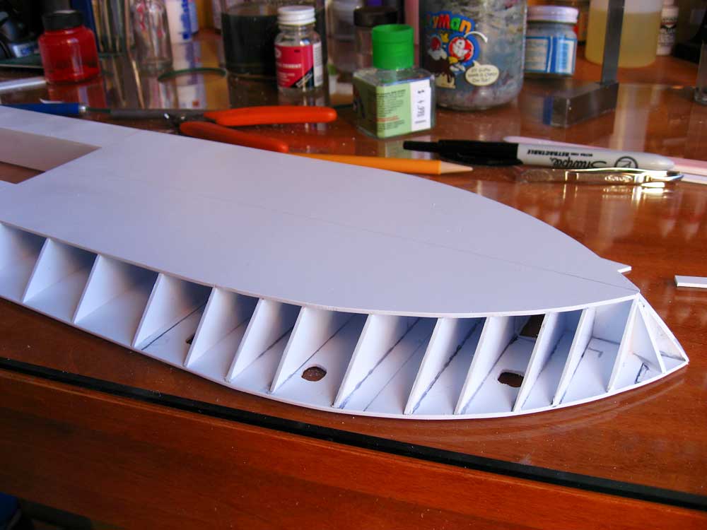
With all of the frames laid in I decided to cut out the bottom of the hull and revel in the simplicity of the build so far. I believe it was Homer Simpson who said "Doh"! As I said at the beginning, I'm using two sets of plans, the CAD Set from the internet, and the two sets drawn by David Meagher. The CAD drawings showed EVERY frame on the ship as having a 45-degree angle, so I chose them. Now you can see how those were incorrect. The lower hull does not match up to the frames forward and aft (aft not shown here). An easy enough fix: I marked the offending frames where they met the hull, took a pair of pliers and wiggled them until they snapped free, recut them, and then glued them back in place. The next photo shows the frames attached once again and everything matching up much better. |
|
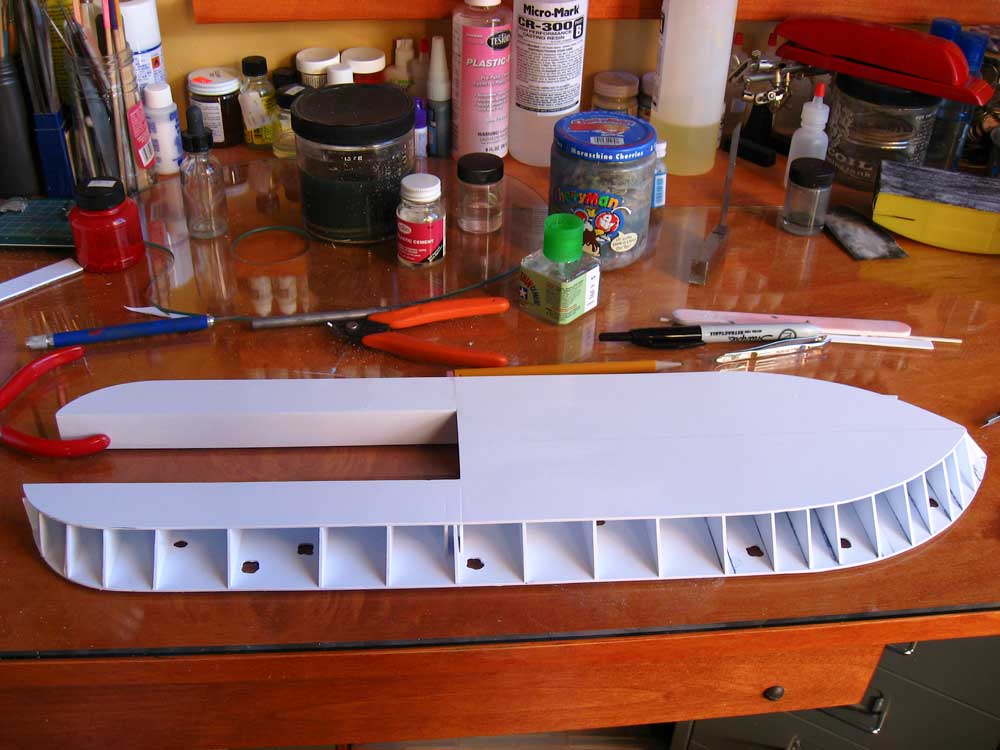
After the bow was matched up, the after portion revealed another problem with the plans. Things didn't match up. Fortunately I was able to rectify the issue by making two cuts in the lower hull and adding a spacer. This was fairly straight-forward, just required adding a couple more frames to make sure everything was firm and secure.
|
 |
Now it's starting to look like a hull! |
|
   |
|
| *February 21st Update* | |
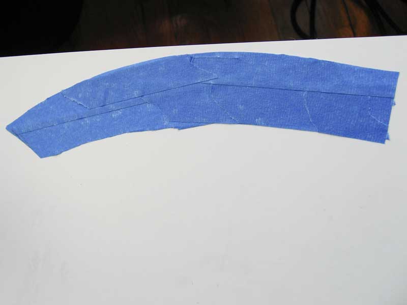
| With the hull bottom, main deck, and all the frames stuck together, it's time to sheet. Along the hull sides where everything's nice and straight, I simply glued in .030 styrene and trimmed to shape. For the curves forward and aft, though, I "plated" the areas with blue masking tape, trimmed it, then stuck it to sheet styrene and cut it roughly to shape with shears. It was then glued to the hull and trimmed and sanded after the glue and styrene had dried. | 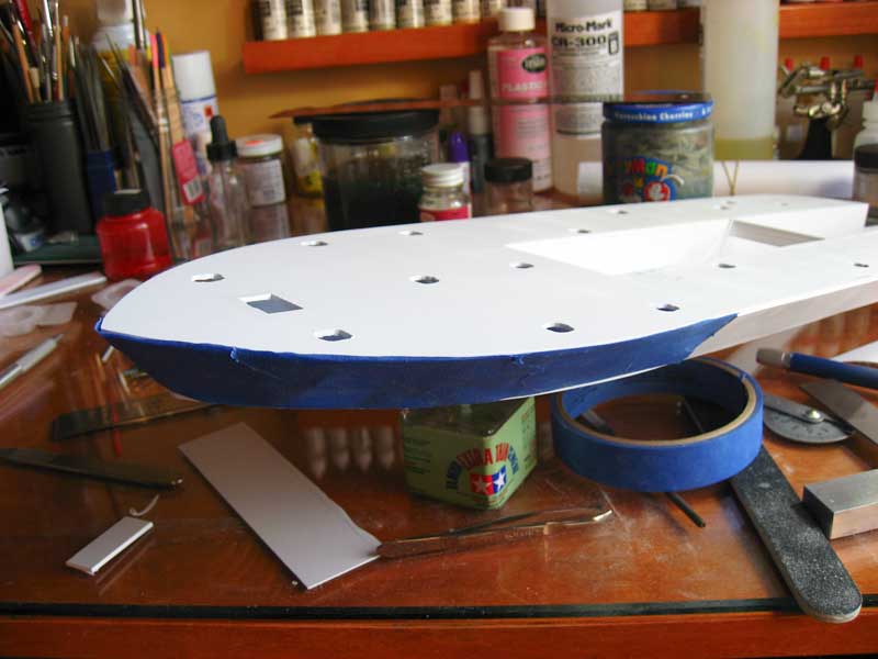 |
  |
|
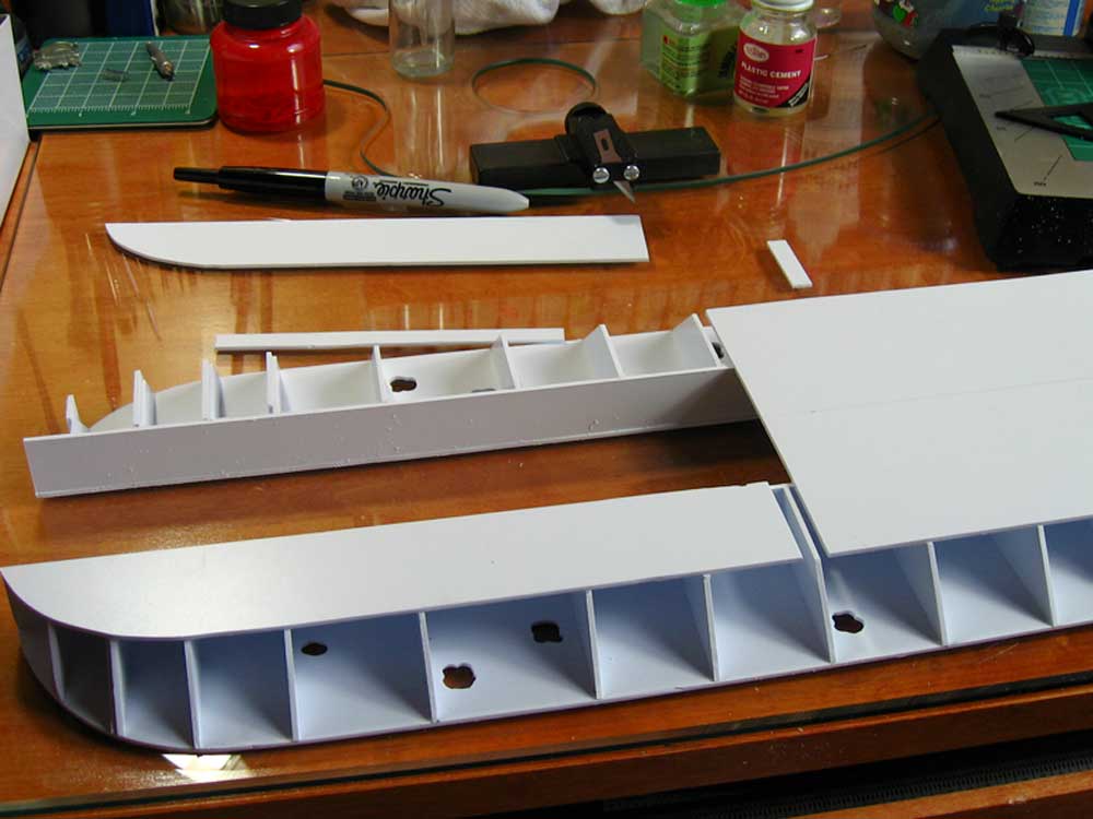
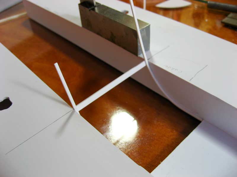
| One of the few curves on a City Class gunboat is on the bottom of the hull, where the flat bottom hull transitions into the paddle wheel well. This is illustrated here, boxed in red, on the David Meagher plans. | 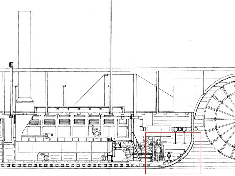 |
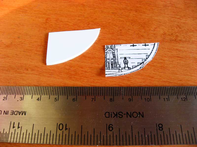
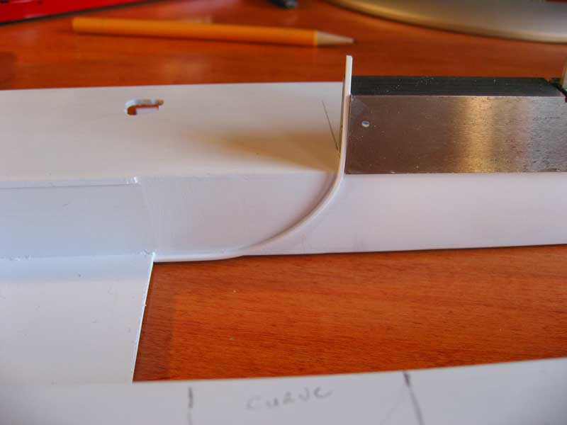
| I transferred this curve to the inside of the hull trough by cutting the curve out of a copy of the plans, taping it to both sides, and tracing it with a pencil. I then affixed one end of a strip of styrene to the lower hull's end in the trough, let that dry, and then gently curved the styrene to follow the pencil mark, careful to make sure that the ends of the strips on both sides broke the surface of the main deck at the exact same point. Here I show one plank installed, before the curved sections were cut flush with the deck, to make sure everything lined up. Eventually the entire curve will be planked with strips of styrene like this. I need to allow for steam exhaust piping, however, and I'd rather wait until the boilers and piping go in so I can cut the planks before attaching, rather than doing a retro-fit. | |
   |
|
| This is how she sets now. At this point I'm filling gaps with styrene and using my rasp file and sandpaper to make sure everything is straight. I don't have to be too concerned with neatness at this point, as everything shown will be planked with another coat of styrene, but I still find myself obsessing over little things. That's half the fun of it, I suppose. | 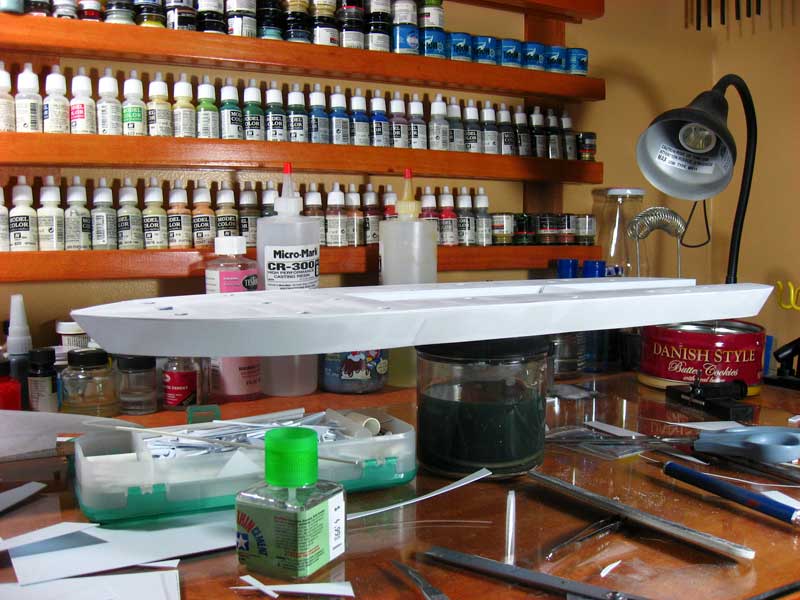 |
| *March 25th Update* | |
| Not a lot of progress due to travel and writing, but I wanted to put up something since it's been over a month. Above I stated how I don't have to be too concerned with neatness at this point, as this skin over the hull is the first of two. I do, however, want to fill any major dips so that the planking doesn't run too wonky. Enter Aves Apoxie Sculpt. This is much like your basic two-part putty. I use it almost exclusively. It's more time intensive than something like hobby putty or Bondo as it must be mixed and it takes a day to dry. The benefits are that there is no shrinkage when dry -- absolutely zero -- and if you use it to build up an area you can then sand an edge down until it's a razor sharp edge, or as a filler it will feather out until it's translucent. You can roll it into a tube, let it dry, and work it in a lathe. I've never seen a putty that works as well or is as versatile as this stuff. | 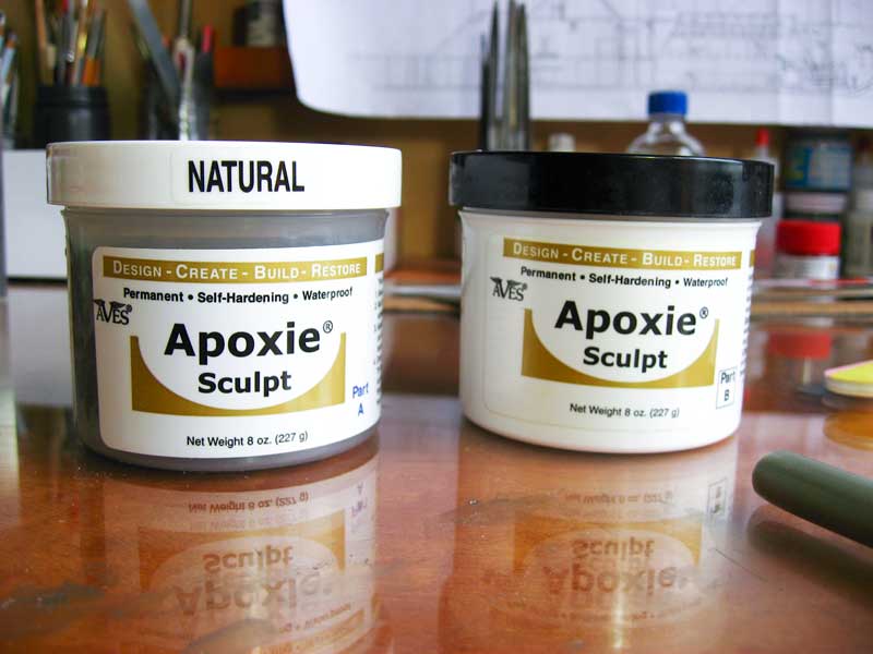 |
Here you can see where I have applied the Aves to the hull. When I sheeted the hull I started with the straight runs amidships and fit them between the two decks. When sheeted forward and aft, though, I put the sheeting on the outside of the deck radius. Not a big difference, but it's a better bond, and I ended up with a step-down in in those areas. *Note my cool make-shift holders for rolled plans!* |
 |
| This is it sanded smooth -- mostly, I put a little dab more in a gouge that I made while sanding -- and you can see how it feathers down to almost nothing when sanded. I don't want a lot of it on the styrene for this purpose as I want as much of a styrene-to-styrene bond between this layer and the next as possible. | 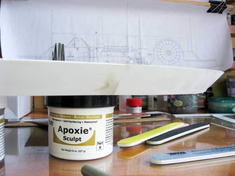 |
| Another bit of work as to do with starting the keel. This is something that had I thought it out further before I started then I would have made this an actual structural keel going from the bow to the fore end of the engine room, but I didn't, so live and learn. When I sheeted the bow area I left a gap and then fit this piece of rectangular styrene stock. I used a lot of plastic cement and my machinists squares to make sure it's all true and straight. The gaps along the side will be covered by the fitted planking in the next pass. | 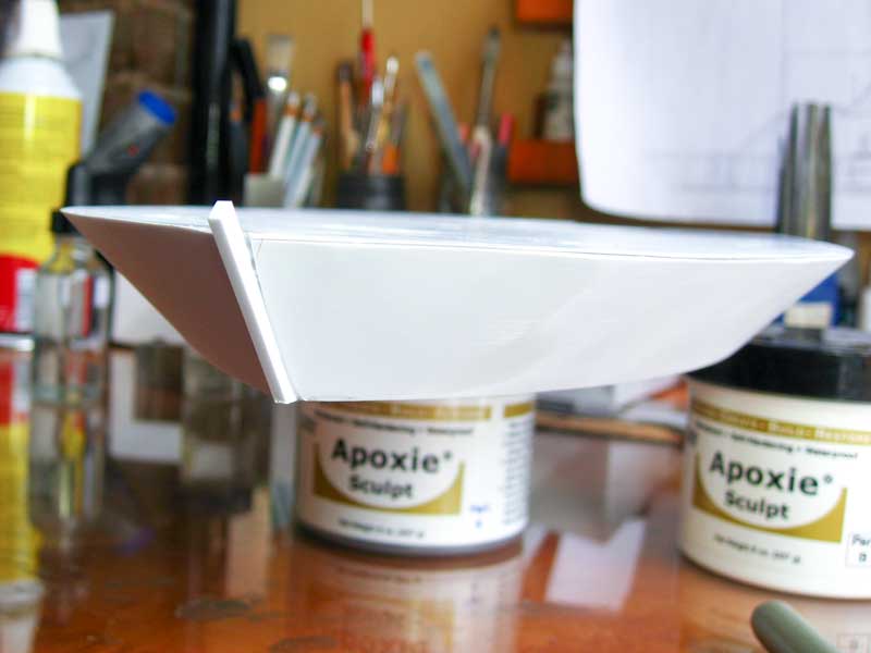 |
Now I'm waiting for the rest of the Aves putty to dry, sand that out, then I get to extend that keel on the bow to the lower hull and start planking the bottom of the hull. Also, check out the new Reference and Supplies page. |
|
| *May 9th Update* | |
Very busy lately. Long time, no update. Here's a little something... I realized that I hadn't fixed any bolts inside the hull to mount it to the base. I opened up a couple of the holes in the deck and put them inside, positioned them with a paint brush handle, tacked them in place with super glue, then packed epoxy putty around them to get a solid join. |
 |
| Here's the curve between the lower and upper hull that I showed started a few posts ago. Now I've finished planking the curve. | 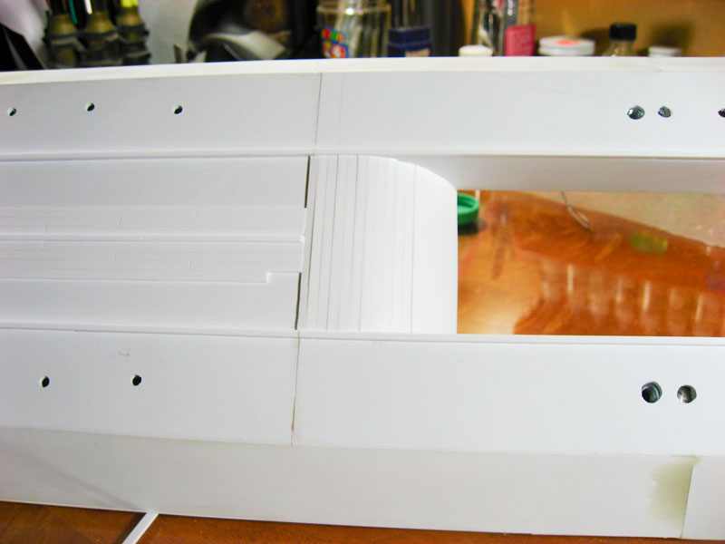 |
| The City Class had three keels. Here's the centerline keel with the upturn for the bow. Nice, simple 45-degree angle here. |  |
| Here's the rear end of that centerline keel, attached to the hull. I had to rip this piece out once as it was WAY off of the center line. Working backwards I found a measurement here and there off by only a millimeter or two which added up the problem. A lot of sanding and swearing and re-measuring fixed the issue. | 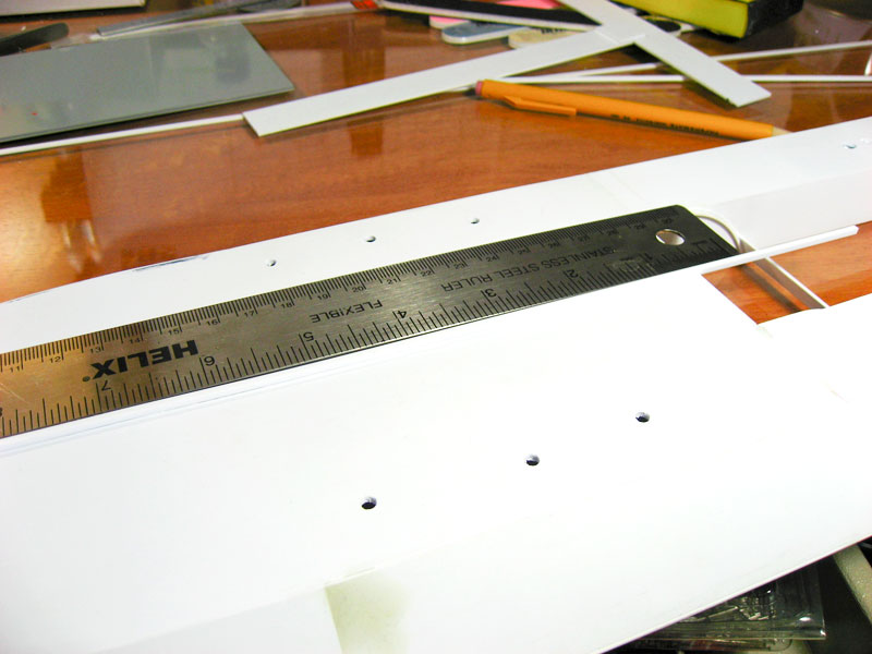 |
| Here's where I sit now. The three keels are clearly visible here. I've started planking the lower hull. I'm using Evergreen strip styrene, 3mm wide by 1mm thick, cut into 103mm lengths. It's slow, tedious, yet rewarding work. I'm leaving the keels and the planks proud of the hull edge for now so that I can trim and sand them all at the same time for a uniform finish. | 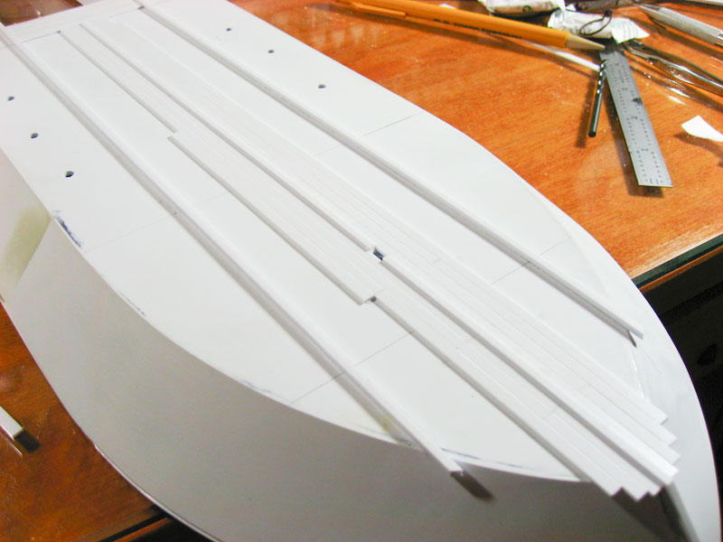 |
| *June 13th Update* | |
It's kind of repetitive to say how busy I've been lately, but it does impact the modeling time. I continue with the tedious task of laying the 1mm X 3.2mm X 102mm planks. Each plank is cut to size, all four edges of the top surface scraped with a scalpel to knock off the sharp edges and give definition between the planks, and then glued down. I'm laying them in a staggered pattern of 4 rows before I repeat the pattern. I futzed around with the contrast and such on this photo so that hopefully you can see what I'm talking about. That's it for now, but I believe I might have worked out how to begin laying out the casemate, something I've been pondering for a couple of months. Hopefully I can proceed soon, or at the very least finish planking the bottom of the hull and move to the hull sides, which will be done in the same manner as the bottom. |
 |
| *July 5th Update* | |
| A major milestone has been reached: I have finished planking the bottom of the hull! I'm happy with it, so I'll be using this process for the rest of the ship. A couple of quick photos of the bow and stern sections here. |  |
| These are before-and-after shots of a sort: on one side of the hull the planking is still sticking out before being trimmed. On the other side I've trimmed them and sanded flush with a very firm sanding block and metal files; you can't have any flex in the sanding medium in this area. | 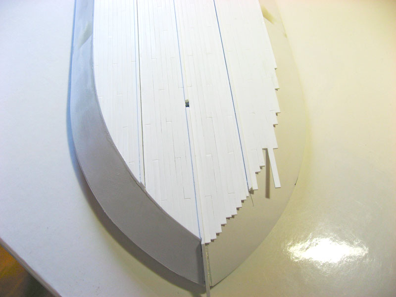 |
| I've finally decided on the method for building the casemate. I'm starting with a sheet of .040" styrene, cut to the shape of the deck and as long as the base of the casemate. I'll cut this out, and then cut out the majority of the interior of this sheet as well. The idea is to have a thin sheet all of the way around, sort of like a footer for the wall in a house, to build the side timbers upon. This might be a little backwards and odd way to go about this, but right now it makes sense to me. |  |
| *October 13th Update* | |
An embarrassing long time since an update, but work, vacation, writing, blah blah blah... This is a single shot of the beginning of the gun deck and casemate construction. I've decided that I want the casemate to be a separate assembly for ease of interior detailing. This is the start of it: the "floor" of the gun deck is taped to the hull, the forward and aft ends of it are where the casemate will meet the deck. (note, this is a different piece than I had in the previous post, I had to cut it again, got a little overzealous the first time!) I have it taped in place for final shaping, and I drilled four holes and have inserted wire to help hold it in place, and also to key the assembly so that I can line it up exactly as construction progresses. The other sheet in the foreground is the top of the casemate, or the hurricane deck. The next step is to take the casemate bottom and the hurricane deck, sandwich a sheet of pink insulation foam between them, then start sanding to shape. We'll see how this goes... |
 |
| *November 14th Update* | |
| Picking up from the gun deck decking photo above. Here it is being glued to a sheet of ordinary pink insulation sheet foam. I got lucky (again) and the sheet foam's thickness of 1" turned out to be the exact height I needed between the casemate floor and roof. I used white glue for this step as the foam will be coming out and I want that process to be as easy as possible. |  |
| Once that was done I flipped the assembly over, centered and aligned the sheet styrene for the top of the casemate, and glued that to the foam using white glue as well. | 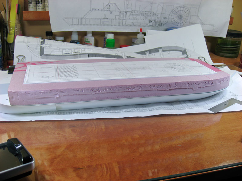 |
| When the whole sandwich dried, then I shaped it. I started with a coarse rasp file, switched to a fine one, then did the final sanding with 150 grit sandpaper in a sanding block. The rasp made quick work of the foam, almost too quick at times. The foam sands and shapes very well, though. | 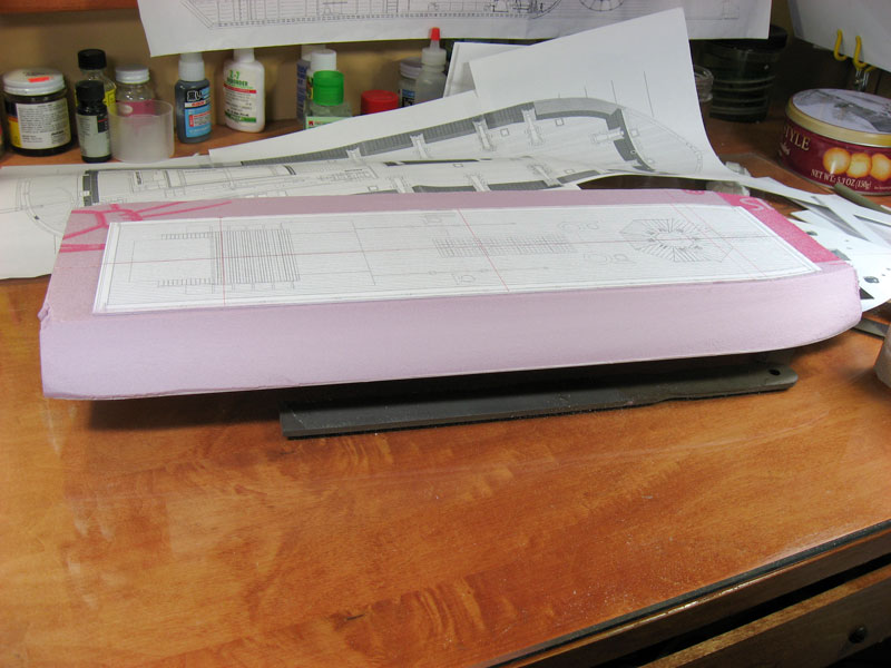 |
| All of the rough sanding done, most of the fine work as well. There are some gaps that I will fill with spackle before I sheet over the foam with more styrene for the casemate sides. Here's an overall shot; besides the pink color it's starting to look like a gunboat. | 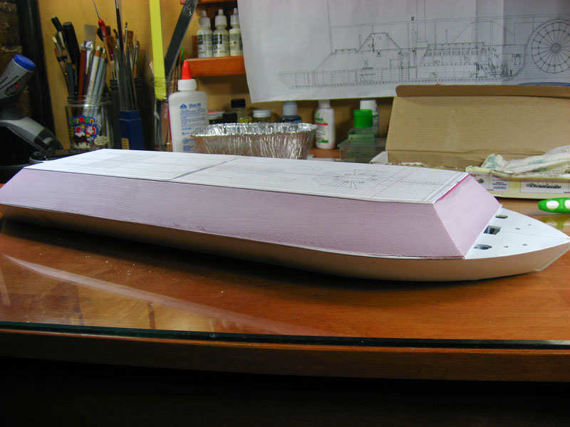 |
| Here's a view of the stern, showing how well the foam blends to the curves. There's a little more work to be done to get it all lined up and right, but it's darn close. |  |
| I've also started thinking about what I'm going to put in the interior of this thing. Here's the five styrene tubes that will make up the boiler assembly. |  |
Construction continues... |
|